Introduction
Epoxy-based hermetic feedthroughs have worked well in cryogenic systems for years. But the
design modifications needed to operate in these extremely cold temperatures increased the size
of the feedthrough and limited your mounting options. We recently eliminated these issues
with an entirely new approach to cryogenic feedthrough design.
Intended for use in space simulation, laboratory and liquefied natural gas systems (LNG), our new cryogenic feedthroughs do away with a bulky compression system found on previous designs. Our new design also supports all the common feedthrough mounting styles—including threaded, welded, bolted, or vacuum Conflat. Here’s a closer look at the new cryogenic feedthrough technology and the design strategies that made it possible.

Overcoming Coefficient of Thermal Expansion (CTE) Issues
In a typical hermetic feedthrough design, the epoxy seals are cast around copper conductors within a metal fitting made from stainless steel, brass or aluminum. This standard design approach delivers reliable hermetic performance as long as temperatures stay within an operating range of -70 to 300ºF. However, as temperatures plunge to cryogenic levels, the coefficient of thermal
expansion (CTE) mismatch between the epoxy and metal fitting creates an increasingly serious problem (See Figure 1).
Keep in mind that the CTE mismatch problem only affects the seal between the epoxy and the metal fitting, not the seal between the epoxy and the copper conductors, which have a CTE of 17x10-6/ºC. At cold temperature the CTE mismatch of the epoxy relative to the copper actually works in our favor— by compressing the epoxy around the copper and increasing the hermetic performance.
But that still leaves the CTE mismatch between epoxy and the fitting. Historically, to work around this issue, our engineering team devised a cryogenic design in which the seal to conductors occurred in an epoxy slug. This slug would then be tightly compressed between two metal flanges and a metal O-ring (See Figure 2). This design approach did control the CTE mismatch and offered hermetic performance, but it added bulk and cost to the feedthrough. And it could only be bolted on, limiting
your integration options.
Work With The Mismatch, Not Against It
Our new cryogenic feedthrough design takes a more elegant approach that does away with the metal gaskets and compression flanges. Instead, we seal the epoxy directly to the metal fitting. To make this direct seal approach work, we found a way to use the CTE mismatch between epoxy and metal to our advantage.
Like a traditional feedthrough, the new cryogenic design casts the epoxy around the conductors within the metal fitting. The exterior of the fitting, however, has been modified with a small interlock feature. The epoxy flows around this feature during the casting process, creating a mechanical bond between the two materials. That bond gets stronger the more the epoxy shrinks relative to the metal (See Figure 3).


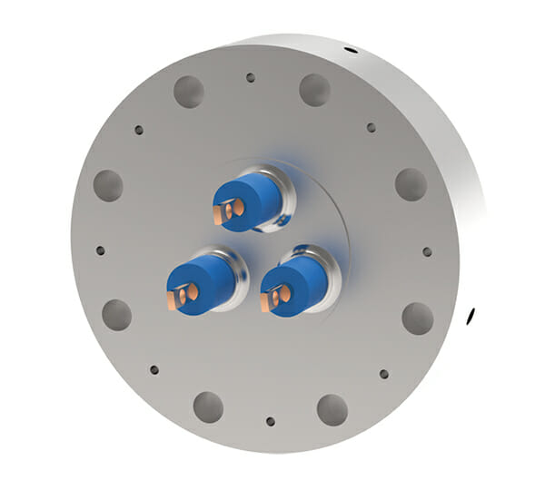
Figure 3: Douglas Electrical’s new cryogenic feedthrough has an internal feature that takes advantage of the CTE mismatch between epoxy and stainless steel to create a low-temperature hermetic seal. This new design does away with the need for the separate metal O-ring required by previous cryogenic feedthroughs.
Stress Analysis
Our new approach to cryogenic design sounds simple enough, but it did require us to fire up design tools not commonly applied to conventional feedthroughs. For example, we ran extensive finite element analysis (FEA) simulations to optimize the design of the epoxy-metal interface (See Figure 4).
It turns out that we had to manage stresses at the interface within a very tight band for this design to work not only at cryogenic temperatures but also high pressures (2000psi) and high temperatures (300ºF). We ultimately went through dozens of design iterations and several epoxy formulations on
our way to launching this new technology. The FEA work did not replace the need for real world testing, but it helped identify excessive stress buildups at the epoxy-metal interface and quickly optimize our design for a wide range of temperatures and pressures.
True Hermetic Performance
All the FEA and design optimization work paid off. The direct seal cryogenic technology provides true hermetic performance in challenging conditions, including:
- Helium vacuum tests <1x10⁻⁸ cc-He/sec after every environment exposure.
- Cryogenic dwells in liquid nitrogen at –321ºF.
- Pressure testing to 1,800psi of nitrogen after each thermal exposure.
- Thermocycles from –95ºF to 125ºF while under constant 1800psi pressure.
- Thermal shock tests with immediate change from 75ºF to –321ºF followed by 1,800psi pressure.
- In all cases, the feedthrough design maintained leak rates under 1x10⁻⁸ cc-He/sec and experienced no failures related to thermal conditions.


Figure 3: Douglas Electrical’s new cryogenic feedthrough has an internal feature that takes advantage of the CTE mismatch between epoxy and stainless steel to create a low-temperature hermetic seal. This new design does away with the need for the separate metal O-ring required by previous cryogenic feedthroughs.
Easy to Implement
The direct seal cryogenic feedthrough technology can be applied to a variety of our feedthrough products—including DuctorSeal®, PotCon® and StudSeal™. And because it adds no bulk and supports all the common mounting styles of these products, the new direct seal feedthroughs can be easily integrated into a wide variety of space simulation, LNG, laboratory and industrial systems.
For more information on our hermetic feedthrough designs for cryogenic applications, visit:
PDF: Cryogenic Feedthrough Capabilities Brochure PDF
Featured Feedthroughs

DuctorSeal

Portplate
